Cladding · 15 MINUTE CPD
Rainscreen Cladding: Inspecting Behind the Panels
A 15-minute guide to the concealed parts of rainscreen façades: supports, weather protection, insulation and cavity barriers. Learn how to check interfaces and keep evidence by elevation and stage.


The finished panels are only the visible part of a rainscreen façade. Behind them are supports, insulation, weather-control layers, drainage paths and fire-protection details. This CPD helps you plan inspections that connect those parts to the coordinated design before access disappears.
Your 15-minute activity: allow 10 minutes for reading and three diagrams, three minutes for the scenario and two minutes for reflection. Regulatory references are for England. This activity does not assess the compliance of an existing building or provide a façade design.
1. Separate the functions, then coordinate them
A drained and ventilated rainscreen arrangement manages rain at the outer face and within a cavity. Its backing construction and weather-control details must also manage moisture at openings and interfaces. The project detail establishes the intended route; it should not depend on hoping every panel joint stays dry.
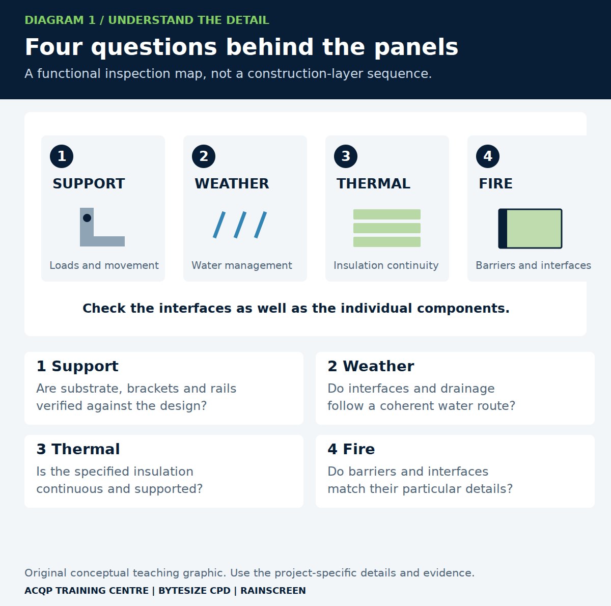
At the same time, the façade must transfer loads, accommodate movement and deliver the required thermal and fire performance. Diagram 1 separates four inspection questions rather than showing a buildable section. Use it to identify the relevant drawings and specialists.
Approved Documents provide guidance on different requirements, but reading one does not resolve the whole façade. Confirm the building's applicable requirements and the edition and transition arrangements relevant to the project. Government: Approved Documents
2. Inspect the supports before panels arrive
Compare the substrate, anchors, brackets and rails with the current setting-out and structural details. Check product identification, location, specified connections and the required inspection or testing records. Do not derive an anchor's capacity from its appearance.
- Locate the work by elevation, level and bay.
- Check that the actual substrate matches the design assumption.
- Verify the bracket and rail arrangement, including movement provisions.
- Identify required thermal isolators and compatible components.
- Record deviations, unplanned packing, damaged parts or altered holes for assessment.
A bracket moved to avoid a service or an anchor installed in a different substrate may need a design decision. A panel that fits does not prove that the support arrangement is correct.
3. Trace weather protection through the interfaces
Review membrane identity and the specified arrangement of laps, seals, terminations and penetrations. Inspect interfaces around openings, brackets and changes of material while accessible. Establish how water will discharge at the base and at interruptions without being directed into the building.
Distinguish moisture-control products from fire-protection products. A membrane or EPDM strip may serve a weatherproofing function; that function alone does not make it a firestop or cavity barrier. If a component is claimed to satisfy another role, request the relevant evidence for that use and arrangement.
Approved Document C provides the moisture-resistance context. For inspection, use the actual coordinated façade details rather than applying a generic sketch to every window or bracket. Approved Document C: moisture resistance
4. Check cavity barriers by product and orientation
Locate each required barrier on the fire strategy and façade details. Verify its exact identity, supporting construction, position, orientation, fixings, joints, intersections and relationship to insulation and panels. A strip of a familiar material is not sufficient evidence.
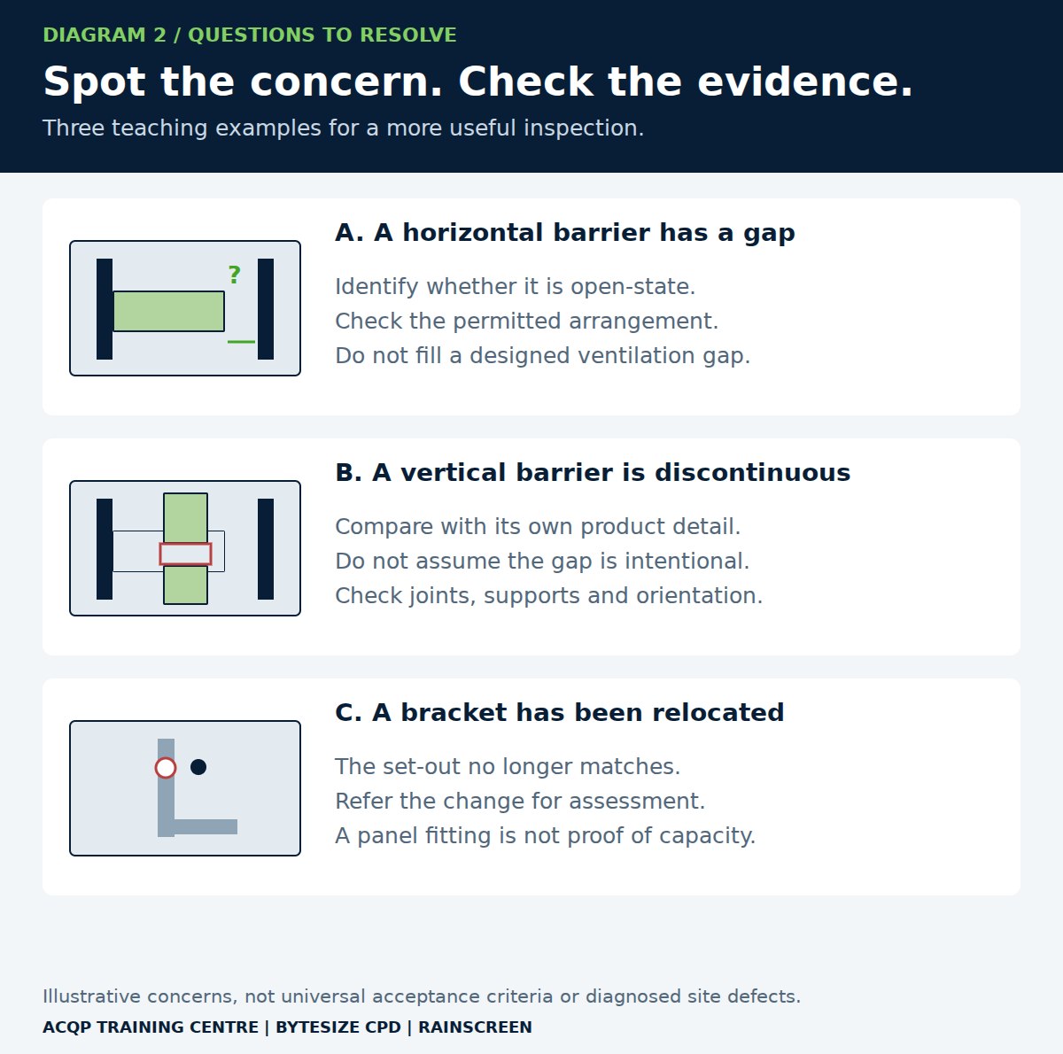
Some horizontal open-state cavity barriers preserve a defined ventilation gap in normal use and close it under fire exposure. Siderise RH is one manufacturer example. This does not mean every barrier is open-state or that the same gap applies to every product. Use the selected product's evidence and installation instructions. Manufacturer example: open-state barriers
Check the installed gap or contact condition as specified. Do not pack an intended ventilation gap with spare insulation, rotate a barrier or substitute a vertical arrangement for a horizontal one without an appropriate technical decision. Diagram 2 illustrates why a gap can be either a deliberate feature or a defect depending on the detail.
5. Build a record by elevation and stage
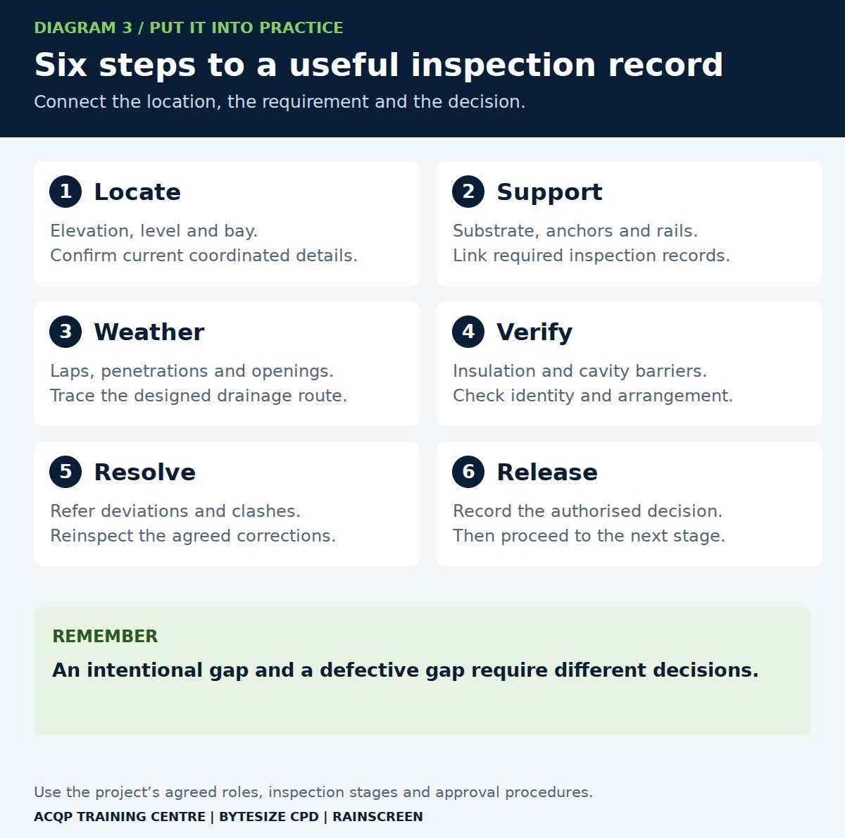
Organise evidence around identifiable façade bays and inspection stages: substrate and anchors, support system, weather layer, insulation and barriers, then panels and interfaces. Keep product records and any test results linked to those locations.
Use overview photographs to establish location and close views to demonstrate the particular check. Record measurements where required and show which detail revision was used. State limitations: a photograph of the outer panel cannot establish a barrier's hidden fixing.
Coordinate the next trade so unresolved questions do not disappear behind panels. Any design change must follow the project's technical and approval processes, including additional procedures where applicable. Quality inspection supports those processes; it does not replace them.
Site scenario: a gap that looks wrong
Before panels are fitted, you see a gap at the front of a horizontal cavity barrier. One installer proposes filling it with insulation. Elsewhere a vertical barrier has a visible discontinuity, and a bracket has moved from the setting-out drawing to avoid a pipe.
Pause for three minutes: Why should these three observations not receive the same response?
Suggested response: first identify the horizontal product and determine its required open-state arrangement, including the permitted gap. Check the vertical discontinuity against its own detail rather than assuming it is intentional. Refer the bracket change for the required structural and coordination decision. Record locations, retain access and verify the resolutions before release. “Fill every gap” is not a competent façade inspection rule.
Take this to your next inspection
Choose one bay and follow each requirement to its evidence: support, weather protection, thermal continuity and fire protection. Identify any interface for which two trades are relying on incompatible details.