Brickwork · 15 MINUTE CPD
Wall Ties: Small Components, Important Connections
Check tie identity, actual cavity width, embedment and local details before the wall hides them. Includes a scenario on a widened cavity and a clear sequence for recording concealed restraint.


A wall tie is a small component with a structural job. Once the wall progresses, much of its installation becomes difficult to inspect. The useful time to check its identity, position and connections is while the work remains accessible.
Your 15-minute activity: allow 10 minutes for the article and three diagrams, three minutes for the scenario and two minutes for reflection. This activity concentrates on new-work inspection questions. It is not a remedial tie design or a universal schedule of tie spacings.
1. Identify the wall and the specified connection
Wall ties and restraint fixings connect masonry to another leaf or supporting construction and contribute to stability. Products differ for masonry, concrete, steel framing and timber. A familiar shape or a box described as 'wall ties' does not establish suitability for the wall being built. Leviat Ancon: restraint systems
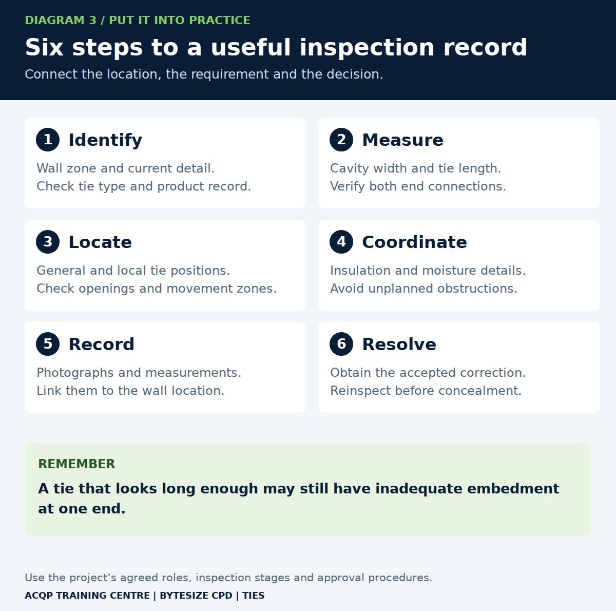
Start with the wall reference, location, current drawing and specification. Match the supplied product, material and length to the scheduled item. Keep the packaging or product record available until the installation record is complete. Check how the wall's temporary stability will be maintained as construction proceeds.
Where a contractor proposes an alternative, obtain the required design review before use. A product may be suitable in one wall and unsuitable in another because the substrate, cavity, exposure or movement arrangement differs.
2. Relate length to the actual cavity
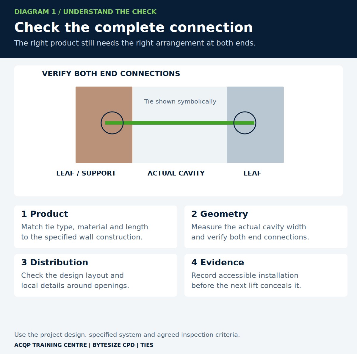
The tie must achieve its specified connection at both ends. In masonry-to-masonry construction, a tie can be too short for the actual cavity, or embedded too deeply in one leaf so that too little remains for the other. Measuring only the delivered tie length misses the second problem.
Compare actual cavity width and the installed position with the required embedment. Where the leaves are built at different times, agree how the eventual outer-leaf connection will be checked. A photograph of a tie projecting from the inner leaf cannot establish the final embedment in the outer leaf. Leviat Ancon: embedment checks
If the cavity varies, record where and by how much. Ask the responsible designer to resolve the arrangement; do not assume centring a short tie, bending it or moving the wall locally is an acceptable correction. Product-specific requirements and the coordinated design determine the response.
3. Check the layout, including local details
Compare the installed distribution with the current tie layout. Look at general wall areas and the additional or different arrangements required around openings, edges and movement zones. The appropriate pattern depends on the wall and loading; a remembered spacing from another project is not enough. Leviat Ancon: layout and lengths
A practical inspection sequence is to work along a named lift or bay, marking the checked locations on an elevation. This makes omissions at a jamb or return easier to discuss than a collection of unlabelled close-ups. If the drawing does not explain an interface, identify the missing information before the next lift hides it.
Keep movement requirements in view. Ties to timber frames, for example, may need to accommodate differential movement. A masonry-to-masonry detail should not simply be transferred to that construction. Leviat Ancon: timber-frame ties
4. Coordinate the cavity as a whole
Inspect the relationship with insulation, cavity trays, barriers and other components against the coordinated details. Check the specified tie orientation and any moisture-shedding features using the product instructions. Do not alter a tie to make an insulation board easier to fit without an accepted technical solution.
Moisture protection remains a separate function to verify. A restraint connection should not introduce an unplanned bridge of mortar or obstruct a designed drainage route. An insulation retaining clip also does not replace the tie's required structural connection. Approved Document C provides the England moisture-resistance context. Approved Document C: moisture resistance
Where requirements appear to conflict, record the exact products and geometry and seek a coordinated detail. Avoid solving one trade's problem by creating an unseen problem for another.
5. Record the hidden connection
- Identify the elevation, bay, lift and relevant drawing revision.
- Record product identity and the dimensions actually checked.
- Show context as well as the connection close-up.
- Record both ends at the appropriate construction stages.
- Link any correction to the original concern and reinspection.
State sampling and access limitations. An inspection of a few positions should not be written as proof of every hidden tie in the elevation. If earlier work is already concealed and evidence is insufficient, agree the necessary investigation with the responsible team.
Site scenario: the cavity has grown
A wall is being built with the scheduled ties. At a return, the actual cavity is wider than shown. Several ties appear deeply embedded in the inner leaf. The outer leaf is about to continue and the bricklayer says the same ties were used successfully elsewhere.
Pause for three minutes: Which dimensions and records would you obtain before work proceeds in this area?
Suggested response: identify the affected bay and product, measure the actual cavity and available connections, and compare these with the applicable requirements. Refer the discrepancy for a checked solution and retain access through the agreed site procedure. Record the decision and inspect the corrected installation at the relevant stages. Another wall's satisfactory appearance is not evidence for this arrangement.
Take this to your next wall inspection
Choose one tie location and ask whether your record will show the complete connection after the wall is finished.