Insulation · 15 MINUTE CPD
Insulation: Small Gaps, Big Consequences
Check the installed thermal layer, not just the product label. Learn to recognise gaps and displacement, coordinate junctions and protect designed ventilation routes before closing up.


Insulation performs as an installed layer, not as a stack of compliant products. Gaps, displacement and poorly coordinated junctions can undermine the intended thermal performance. This CPD helps you check continuity, interfaces and evidence before insulation is concealed.
Your 15-minute activity: allow 10 minutes for the article and three diagrams, three minutes for the scenario and two minutes for reflection. Regulatory references are for England. Use the Approved Document edition and transition arrangements applicable to the project; publication of a newer edition does not automatically change every existing project.
1. Trace the intended thermal layer
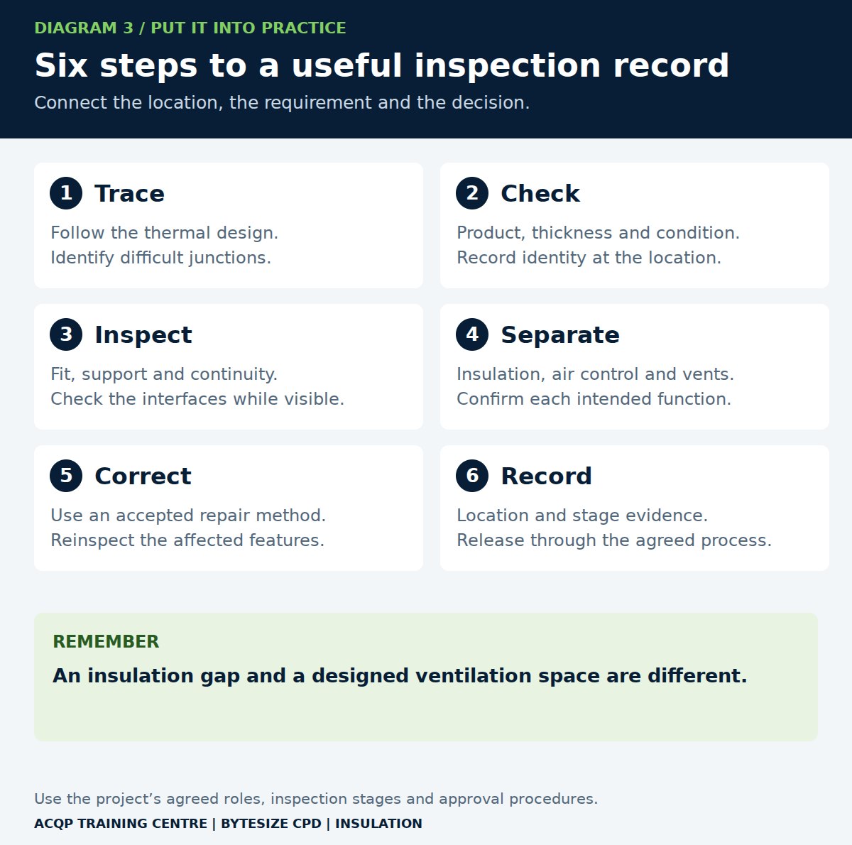
Start with the thermal design and the wall, floor and roof details. Locate the insulation and follow it through corners, openings, changes of level and junctions between building elements. Identify where continuity depends on another trade's work.
Approved Document L explains the importance of insulation continuity and avoiding gaps and thermal bypass. These concerns extend beyond the nominal thickness shown on a drawing. The same document family also includes photographic evidence provisions for relevant dwelling work; establish what applies to your project. Approved Document L: energy performance
Diagram 1 distinguishes a continuous layer from an interrupted one using a simple conceptual pattern. It is not a wall build-up, a U-value calculation or a drawing for installation.
2. Confirm the product and its condition
Match the delivered product to the specified application, declared properties, thickness and any facing or orientation requirements. Keep labels and batch information linked to the work. Two boards with similar colour or thickness may have different properties or intended uses.
- Check packaging, storage and exposure before installation.
- Identify damaged, contaminated or wet material for an appropriate decision.
- Confirm compatibility with adjoining products and required fixings.
- Review any proposed substitution before it is built in.
- Use handling and installation instructions for the selected product.
Do not assume a damaged board can be repaired with any available tape, foam or offcut. Obtain the accepted repair or replacement method and check its completion. Material suitability and workmanship both matter. Approved Document 7: suitability and workmanship
3. Look closely at edges and interruptions
Inspect board or batt joints, corners, reveals, eaves, service routes and the perimeter of floors. These are useful places to compare the intended continuous layer with the actual arrangement. Verify fit and support using the system instructions; do not impose one installation technique on every insulation type.
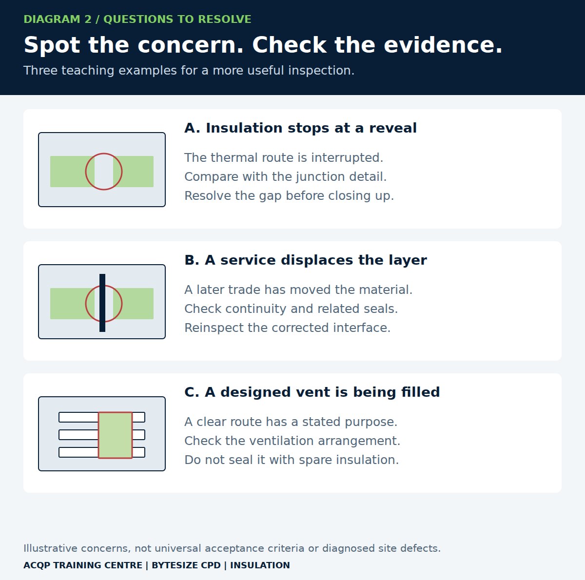
Record gaps, displacement, unsupported pieces, inappropriate compression or missing sections against a location and detail. Establish whether what you see is an unintended interruption or a space deliberately required for drainage, ventilation, movement or another function.
Do not fill every visible void. A ventilated roof or façade may depend on a clear route, and an open-state cavity barrier may require a specific gap. Equally, the existence of a designed cavity does not excuse an accidental gap in the insulation layer. Ask which function each space serves.
4. Keep insulation, airtightness and ventilation distinct
Thermal insulation limits heat transfer. The airtightness layer controls unintended air leakage. Ventilation provides designed air exchange. Some products participate in more than one function, but that must be established by the design and installation details.
At a penetration, check both the insulation arrangement and any required air or vapour-control seal. A photograph of insulation does not prove the adjacent membrane is continuous. Avoid sealing a required ventilation opening in an attempt to improve airtightness.
Approved Document F is the England guidance source for ventilation. Where insulation work forms part of refurbishment, coordinate changes with the ventilation and moisture strategy rather than treating the insulation measure in isolation. Approved Document F: ventilation
5. Capture evidence before the surface is closed
Plan photographs around the junctions and stages that matter. Include an overview identifying the plot or room, then a close view of the feature and any required measurement. Record the product and drawing reference. A photograph of an unopened pack proves neither location nor installation.
Use the agreed inspection plan to decide which checks require direct access, measurements, records or tests. If thermal imaging is commissioned, use a competent person and appropriate conditions; do not treat a colourful image as a substitute for all the checks that could have been made during installation.
Following correction, reinspect the affected area before concealment. Record whether nearby work needs further checking: one displaced board may be isolated, while repeated gaps may indicate a cutting, sequencing or supervision problem.
Site scenario: “the plasterboard will cover it”
At a window reveal, the insulation stops short of the coordinated detail. Nearby, a service has displaced another section. A separate gap at the eaves is identified on the drawing as a ventilation route. The installer offers to fill all three spaces with the same expanding foam before boarding.
Pause for three minutes: What distinguishes these locations? What must be established before accepting a correction?
Suggested response: compare each location with its detail. Resolve the reveal interruption and displaced section using a method suitable for the specified system, including related air or vapour-control work. Keep the designed eaves ventilation route clear. Record the work and reinspection rather than accepting a generic filler for all three. Refer an unclear or unbuildable interface for a coordinated decision.
Take this to your next inspection
Trace the insulation around one room or bay on the drawings, then do the same on site. Where the two routes differ, identify the cause, the decision needed and the evidence required before closing up.